Introduction
Permanent magnets are the unsung heroes of modern engineering, powering everything from electric motors to medical devices and designing with them. That’s where things get tricky. Finite Element Analysis (FEA) is your trusty sidekick, helping you model, tweak, and perfect your designs before they hit the workbench. Whether you’re working with Neodymium magnets, SmCo magnets, or Ferrite magnets, this guide will walk you through the essentials of FEA design for permanent magnets—without drowning you in jargon or scratching your head.
Let’s dive in and explore how FEA can transform your magnet designs into something extraordinary.
Why FEA Matters for Permanent Magnet Design
Designing with permanent magnets isn’t just about picking the strongest one and calling it a day. You’ve got to account for magnetic fields, material properties, and how they interact with your system. That’s where Finite Element Analysis comes in—it’s like a crystal ball for engineers.
FEA lets you:
- Simulate magnetic flux and field strength.
- Predict how Neodymium or SmCo magnets will perform under stress or heat.
- Optimize your design to avoid costly prototypes.
Imagine you’re designing a wind turbine generator. You want maximum efficiency from your Ferrite magnets but are worried about demagnetization at high speeds. FEA runs the numbers, shows you the weak spots, and lets you tweak things before you’re knee-deep in production. Pretty cool, right?
Key Factors Affecting Permanent Magnet Performance in FEA
You need to understand what drives a magnet’s electromagnetic performance to get the most out of FEA. Here are the big hitters—and how to account for them in your simulations.
• Material Properties
Two numbers define a magnet’s soul: remanence (Br) and coercivity (Hc). Br measures the magnetic field strength a magnet can produce, while Hc shows its resistance to demagnetization. For example:
Neodymium Magnets: High Br (up to 1.4 Tesla) and Hc—powerhouses.
Ferrite Magnets: Lower Br (around 0.4 Tesla), but affordable.
In FEA, plug in accurate material data. A slight misstep, like using generic SmCo magnets specs, can skew your results.
• Geometry and Shape
A magnet’s size and shape aren’t just aesthetics—they dictate field distribution. A thin Neodymium disc might outperform a bulky Ferrite block in the right setup. Use FEA to test shapes and optimize for your needs.
• External Magnetic Fields
Magnets don’t work in a vacuum. Nearby steel, coils, or other magnets create external fields that can boost or disrupt performance. In your FEA model, include these interactions for a real-world picture.
Step-by-Step Guide to FEA for Permanent Magnets
Now, let’s roll up our sleeves and get practical. Here’s how to use FEA to design with permanent magnets like a pro.
Step 1: Define Your Goals
Start by asking: What’s this magnet supposed to do? Are you maximizing torque with Neodymium magnets in a motor? Or stabilizing a sensor with SmCo magnets? Clear goals keep your FEA focused.
Example: A robotics engineer might aim for a lightweight actuator using SmCo magnets that can handle 200°C without losing strength.
Step 2: Build Your Model
Fire up your FEA software—think ANSYS, COMSOL, or SolidWorks—and create a 3D model. Include the magnet, surrounding components, and air gaps. Be precise with dimensions; even a millimeter can reduce your magnetic field results.
Pro Tip: For Ferrite magnets, double-check porosity data. It affects how the field propagates.
Step 3: Assign Material Properties
This is where the magic happens. Input the specs for your permanent magnets:
- Neodymium Magnets: High coercivity (Hc) and remanence (Br)—say, 1.4 Tesla.
- SmCo Magnets: Lower Br but stellar thermal stability (up to 350°C).
- Ferrite Magnets: Lower Br (around 0.4 Tesla) but cost-effective.
Don’t forget surrounding materials—steel housings can amplify or dampen the field.
Step 4: Set Boundary Conditions
Tell your software what’s fixed and what’s free. You might lock the stator and let the rotor spin for a motor. Add external forces like temperature or mechanical stress to see how your SmCo magnets hold up.
Step 5: Mesh It Up
Divide your model into tiny elements. Finer meshes near the permanent magnets give you sharper accuracy, especially for complex fields. But don’t overdo it—too many elements slow things down.
Step 6: Run the Simulation
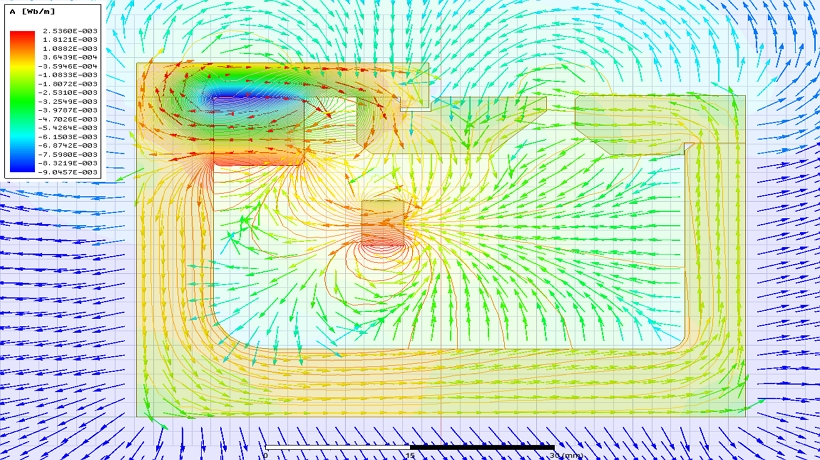
Hit “solve” and let FEA crunch the data. You’ll get colorful maps showing magnetic flux, force distribution, and hot spots.
Step 7: Analyze and Optimize
Study the results. Is your NdFeB magnet too low in magnetic surface field? Tweak the design, perhaps by increasing the size or adjusting the air gap. Iterate until you’re happy.
Case Study: Designing a Magnetic Sensor with FEA
Let’s see FEA in action with a practical example: designing a magnetic steel (magnet) for a sensor.
The Challenge
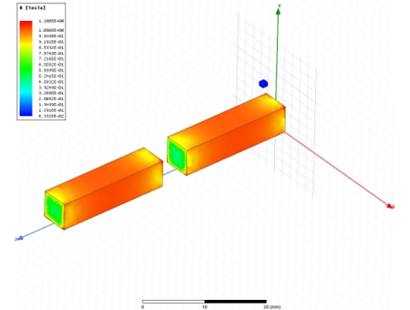
You need two Neodymium magnets for a Hall-effect sensor:
• Placed tip-to-tip, 5mm apart.
• Sensor 4mm from the magnet surface, with a 0-40mm stroke.
• The surface field at ±5mm from the stroke center must be ≥ 70mT.
1. Model
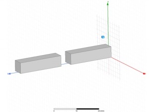
Build the setup in ANSYS Maxwell—two sintered Neodymium magnets, defined spacing. Properties: Assign Br = 1.3T, set magnetization direction.
2. Boundaries
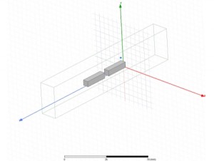
Fix the magnets to simulate sensor movement.
3. Mesh
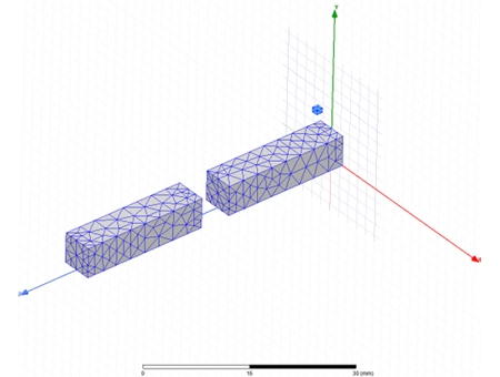
Refine around the magnets for precise field mapping.
4. Run
Solve and validate the model.
5. Results
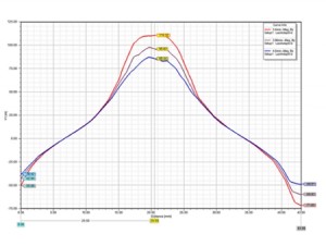
nitial run shows 75mT at the target zone—success! Tweak the shape (e.g., thinner discs) to hit 80mT if needed.
The optimized design met specs with room to spare, proving FEA’s power for even small-scale projects.
Tools and Software for FEA Magnet Design
You don’t need a PhD to run FEA, but you need the right tools. Here are some favorites:
- ANSYS Maxwell: A beast for electromagnetic modeling, perfect for Neodymium magnets.
- COMSOL Multiphysics: Flexible and user-friendly, great for SmCo magnets in complex systems.
- FEMM: Affordable and focused on magnetics.
Pick one that fits your budget and skill level, and you’re off to the races.
Your Next Steps
Ready to harness the power of permanent magnets with FEA? Start small: model a simple system, play with Ferrite magnets or Neodymium magnets, and see where it takes you. For more inspiration, check out these resources on our site:
- [Designing with Magnets: Practical Tips for Engineers]
- [Magnets Selection Guide]
Q&A: Permanent Magnets and FEA Design
Q: Can I use FEA for small-scale projects?
A: Absolutely! Even a tiny sensor with SmCo magnets benefits from FEA to fine-tune performance.
Q: How accurate is FEA for Neodymium magnets?
A: Very—assuming you input precise material data and boundary conditions. Garbage in, garbage out applies here.
Q: Are Ferrite magnets worth simulating?
A: Yes! Their lower cost makes them tempting, but FEA ensures they’ll hold up in your design.
Q: What’s the biggest mistake beginners make?
A: Skipping validation. Always compare FEA results to a physical test when possible.
Got questions? Drop us a line—we’d love to hear about your projects!
There you have it—a roadmap to mastering permanent magnet design with FEA. Now, build something amazing!
Post time: Apr-02-2025